709-218-7927 The Landfall Garden House 60 Canon Bayley Road Bonavista, Newfoundland CANADA A0C 1B0 |
|---|
Rotating Soil Sieve (Trommel)
(1) Motor mounted on top, free from debris and dripping water
(2) Use old bicycle wheel rims - consistent size
(3) Use bucket base and coarse (2") mesh for the barrel structure
(4) Use Bucket base/lids for a prototype
(5) Need a 2' diameter opening so I can toss a shovel of material in easily.
(6) Adjustable incline (lever) to gear speed of travel of material through the sieve
(7) Trommel can be tipped 90º to ease emptying
(8) Rolls on castor wheels ($2-$3 at Swyers)
(9) One wheel/axle is driven from the Rotational Energy Source
(10) Interchange mesh liners, so a two-inch ridded structure
(11) Better: three mesh panels in one pass: fine, medium, coarse, debris
(12) Solid panel to mix (grass, soil, sawdust)
(13) RES can use variable diameter pulleys/cogs
(14) Can operate manually (treadmill?)
(15) Chutes
(16) Cloaks
(17) Gravel washer
(18) Hoops as frames
(19) Roller rims
(20) Taper feed to next
(21)
Tuesday, September 27, 2022
Yesterday Jason delivered three bicycle wheels. I went to sleep tossing ideas in my head.
(1) The cylinder must be open-ended so that material can easily be shoveled in, and can exit from the end
(2) Must have a gradient so that scattered material gravitates to the exit end and does NOT scatter out of the entry end
(3) Spokes must be a minimal number for structural strength or better yet eliminated altogether,
(4) Spokes could be used as string anchor points at, say, six or eight points around the rim; all other spokes can be removed.
(5) Getting a trommel operational is more important than insertable sleeves right now, although I can see me using the coarsest material I have as a basic trommel and having a smaller diameter fine-mesh sleeve that slides in and out fairly readily. In that way I would have a sawdust trommel that can be adapted for fine soil.
(6)
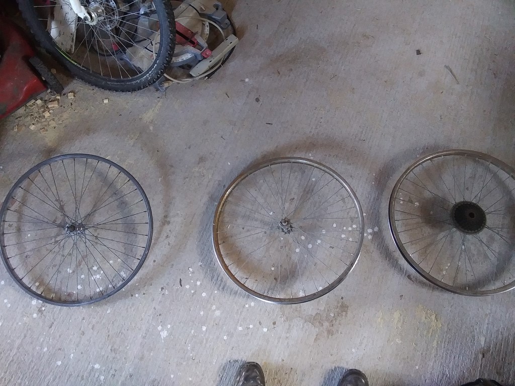
The three wheels on the shed floor. The right hand wheel is a rear axle with five or six gear wheels. If I want to make use of the gear wheel as a driver, I would need to have the gear wheel where it would not be showered with grit, either dropping from the shovel at the upward loading end, or grit tumbling onto it and the downward exit end of the trommel.
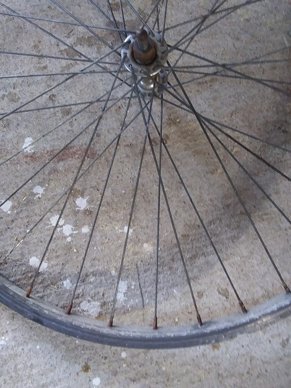
Right now I think in terms of removing all but six spokes, leaving them in for structural stability, but how to thread the mesh around them without removing the spokes and threading them through the mesh.
Originally I had thought of bare rimes, with the mesh tied to the inside of the rim, leaving the outer edge free to run on the castor bearings, and the centre rim to take a belt drive.
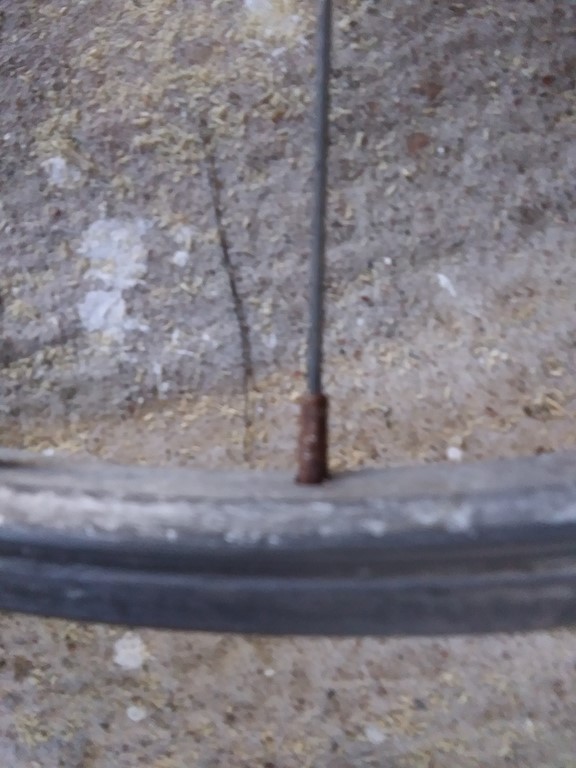
Sixty years ago I used a spoke-key to tighten and loosen the spokes.
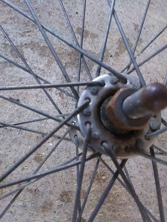
The spokes hook into the hub with a flange-on-a-hook.
Saturday, October 01, 2022
How best to uses a two-wheel frame?
Suppose two bicycle wheels, rims only remove spokes and axle), with four longitudinal pieces of batten bolted to the inside of the rim.
The outside must be left free and as smooth as possible for running on its castors, and for a belt drive.
Of the four bolts, have one bolt longer than the others, long enough to serve as a hook.
Take a length of the coarsest mesh, long enough to fill the circumference plus two or three inches surplus.
The coarse mesh is hooked onto the bolts and then runs around the rim back to the bolts; the mesh could be hooked again.
Repeat this with the next finer mesh and so on ending up with two to four layers of mesh.
Each successively coarser (working towards the first sheet applied) sheets can be removed. The single mesh is the coarsest and that deals with, say, grass clippings and sawdust. A finer mesh will sieve out pebbles, finer still gravel and splinters of rock.
Exchange of sieve is as simple as unhooking from the two bolts, tightening the curve, and sliding a cylinder of mesh out of the trommel.
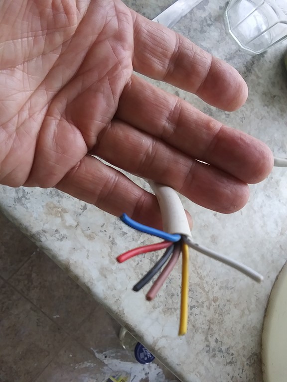
Yes, I have to work out what each of the six coloured wires are. Calls for safety glasses, rubber gloves, rubber-handled pliers, and a length of two-strand wire from a 110v socket.
Sunday, October 02, 2022
Stripped spokes and spoke nuts from two rims. Of course this yielded two ball-bearing axles as well.
Mesh:-
½ inch mesh |
36 |
119 |
|---|---|---|
¼ inch mesh |
36 |
140 |
1" mesh |
36 |
104 |
Rims |
3 |
23" diameter |
1 " |
1/2 " |
1/4 " |
||||
|---|---|---|---|---|---|---|
diam |
circ |
o'lap |
104 |
119 |
140 |
|
23 |
73 |
2 |
75 |
1.4 |
1.6 |
1.9 |
At first glance I can get just one cylinder of each mesh, but in practice If I wrap a ¼" mesh 1.9 times around, then the slight overlap in the mesh on the second turn will give me a slightly finer outfall.
Sunday, October 02, 2022
One front-wheel rim, stripped, sits indoors where I can see it and have it "talk" to me. I visualize four or six 36" battens making a sparse staved barrel. They should be light enough not to add too much to the load, but strong enough to help the mesh hold its shape.
One of the four or six bolts extra-long to retain one end of a mesh strip.
Motive power hurdle: when I thought of a belt-driven system, with a flexible belt running around the rim-as-pulley and a pulley fixed to the motor shaft, that works with the wheel rim supported on a central axle. By removing the spokes I removed the axle, and the rim is to rest on a pair of castor wheels. Four wheels; two for each of the (initially) two rims.
How does the barrel rest on two castors, AND carry a belt around the rim, which belt does not trespass on the castors? The castors will be below the centre of the drum, and be closer together than the diameter. That means that the belt drive must be from below the drum, which is to say, directly under a cascade of debris. The tangent of the belt must part from the rim before the rim reaches a castor.
A chain drive could run inside the rim, and fit between the rim and the castors, but only if the rim was toothed. Toothing can be achieved with bolts whose head is inside the rim and whose shafts act as teeth outside the rim. Bolts drilled through spoke-holes IF the holes spacing matches that of a regular bicycle chain.
Then I need a sprocket mounted on the motor shaft. Advantage is a firmer non-slipping drive for the drum.
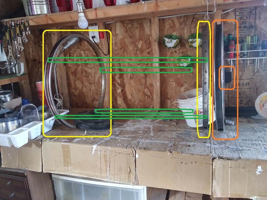
The problem of a belt drive can be solved with a third wheel. The rim at the left is the discharge rim. The yellow and orange rimes at the right are the loading end. The yellow rims sit on castor wheels and bear the load of the drum. The third rim (orange) sits outside the mesh and takes the belt drive.
The belt-drive problem is solved by "splitting" one rim into two rims - one rim to support the drum, and one rim to take the drive.
Now probably four lengths of thin batten (green) will not work. Consider the load of material (clay, rocks) and the force applied to the drive-belt rim. The mesh drum will twist out of shape. Perhaps serious planks will work better. They will interrupt the tumbling of material, like baffles, which might improve the rate of sieving by dropping clods from a greater height onto the mesh. Perhaps they can be braced diagonally across the drum.
The drive rim just happens to have a sprocket, but the sprocket wheel is too close to the size of my motor shaft/boss, so I really would like a chain-driven to the rim. Where to find a 23" diameter chain ring? Answer: Maybe as teeth use short bolts that are entered from the inside of the rim and protrude into the U-shaped exterior of the rim.
A bicycle chain has tooth-holes at one-inch centres. There are thirty-six spoke holes around my rims. The rims are 21.5" diameter at the level of the spoke holes.
36 |
Holes |
|---|---|
21.50 |
inches diameter |
67.57 |
inches circumference |
1.88 |
inch centres |
2 |
3.75 |
3 |
5.63 |
4 |
7.51 |
5 |
9.38 |
6 |
11.26 |
7 |
13.14 |
8 |
15.02 |
Eight spoke holes brings me to a complete set of chain holes, but then that gives me four-and-a-half laps, so two sets of spokes holes/teeth will overlap.
fuzz |
0.1 |
|
|---|---|---|
36 |
holes |
|
21.50 |
inches diameter |
|
67.57 |
inches circumference |
|
1.88 |
inch centres |
|
2 |
3.75 |
|
3 |
5.63 |
|
4 |
7.51 |
|
5 |
9.38 |
|
6 |
11.26 |
|
7 |
13.14 |
|
8 |
15.02 |
8 |
9 |
16.89 |
|
10 |
18.77 |
|
11 |
20.65 |
|
12 |
22.52 |
|
13 |
24.40 |
|
14 |
26.28 |
|
15 |
28.15 |
|
16 |
30.03 |
16 |
17 |
31.91 |
|
18 |
33.79 |
|
19 |
35.66 |
|
20 |
37.54 |
|
21 |
39.42 |
|
22 |
41.29 |
|
23 |
43.17 |
|
24 |
45.05 |
24 |
25 |
46.92 |
|
26 |
48.80 |
|
27 |
50.68 |
|
28 |
52.56 |
|
29 |
54.43 |
|
30 |
56.31 |
|
31 |
58.19 |
|
32 |
60.06 |
32 |
33 |
61.94 |
|
34 |
63.82 |
|
35 |
65.69 |
|
36 |
67.57 |
|
Tuesday, October 04, 2022
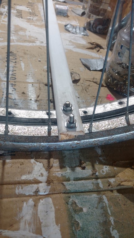
What I had called the loading end of the drum, with its twin rims - a drive rim and a castor rim.
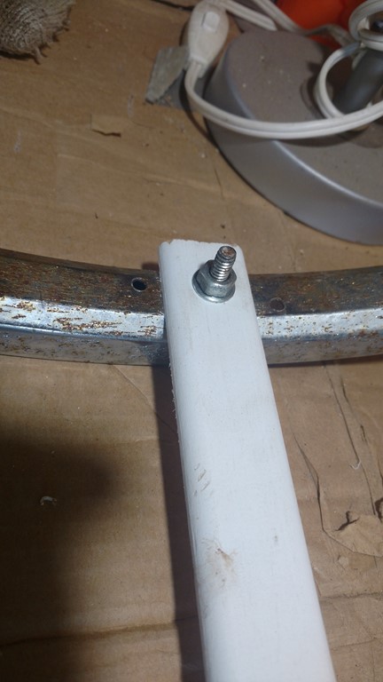
The discharge end with just a castor rim.
The bolts are from my three bolt/washer/nut jars. The batten is possibly too light, too short, the holes dangerously close to the ends. It is a start.
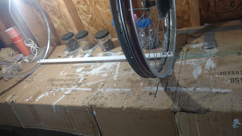
The tacked-together assembly, the rims spaced apart for a 36-inch mesh.
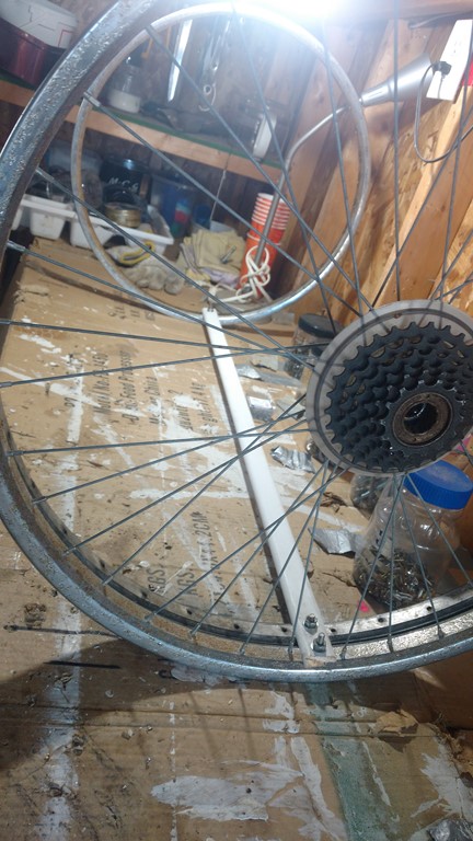
It will not have escaped your notice that the spokes on the drive rim will inhibit shovelfuls of material into the loading end. The spokes must be removed and the two rims drilled and bolted together.
I have not yet designed any flywheel, for rotational momentum. Simplest case would be to wrap a set of half-inch strips of lead around the castor rims, bolted through the spoke holes.